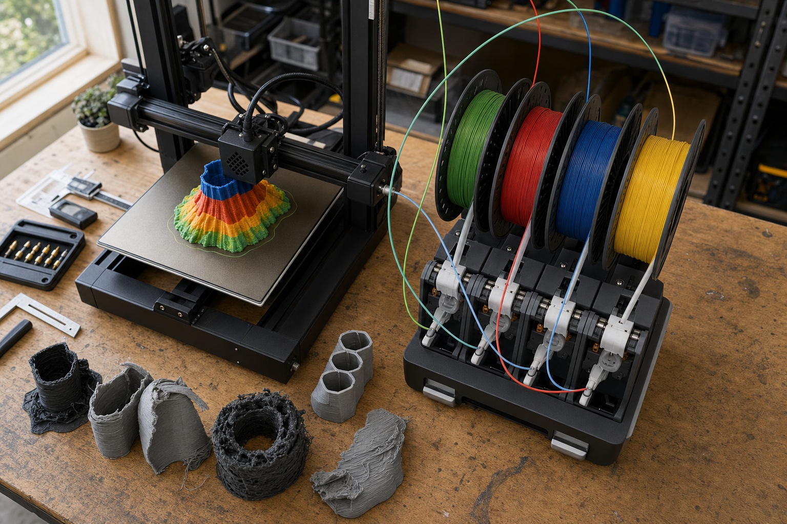
A $99 filament changer swapping colors is not the same technology as a $250,000 PolyJet system blending 14 photopolymers at the voxel level. Confusing them wastes your money. The right approach depends entirely on what you're trying to make: multicolor figurines need a filament changer; rigid-plus-flexible functional parts need a tool-changer or industrial jetting; and property grading across a single wall requires PolyJet at $50K+. This guide maps your goals to the hardware, materials, and design workflows that actually deliver: and the failure modes each path hides.
What "Multi-Material" Actually Means
Multicolor printing, multi-material printing, and voxel-level material grading are three distinct capabilities sold under one label. Mistaking one for another leads to wrong hardware purchases.
| Term | What It Does | Example | Complexity |
|---|---|---|---|
| Multicolor | Swaps filament colors; same polymer properties | PLA figurine in 4 colors | Low: swap filament |
| Multi-material | Combines polymers with different physical properties | Rigid PLA housing + flexible TPU grip | High: requires compatible temps, adhesion, flow |
| Voxel-level grading | Blends materials at microscopic resolution | PolyJet part varying from 30A to 95A shore hardness in one wall | Very high: industrial only |
A printer advertised as "four-color" is not necessarily capable of combining four materially different polymers. Four PLA colors is multicolor. PLA plus TPU is multi-material: a harder problem involving temperature compatibility, adhesion chemistry, and flow-rate matching that no amount of slicer tuning fully solves on a shared-nozzle system.
Multi-Material vs. Multicolor
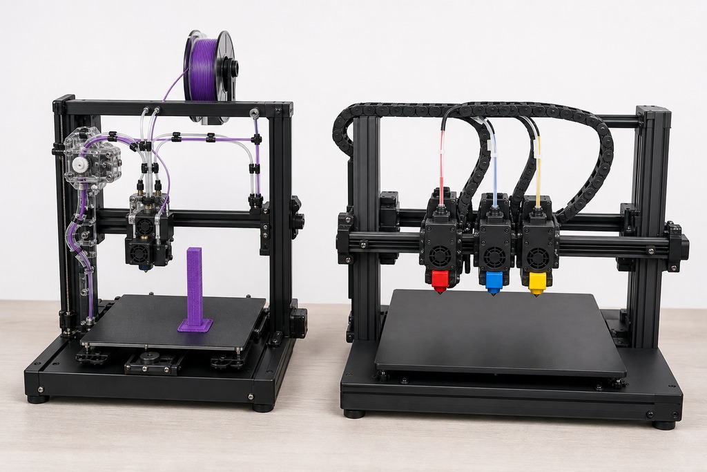
Multicolor printing changes filament colors within one polymer. Mechanical, thermal, and chemical properties stay identical across every color. Multi-material printing combines polymers with genuinely different properties: different melt temperatures, different shrinkage rates, different stiffness or flexibility.
Hardware that handles multicolor trivially can fail at multi-material entirely. A Bambu Lab AMS swapping between four PLA spools is a solved problem. That same AMS feeding rigid PLA and soft TPU through one nozzle encounters filament buckling, inconsistent flow rates, and purge contamination that no slicer setting eliminates.
How Hardware Architectures Switch Materials
The physical mechanism of material switching determines purge waste, print time, and which combinations work at all.
| Architecture | How It Switches | Materials/Job | Switch Time | Purge Waste | Price |
|---|---|---|---|---|---|
| Single-nozzle filament changer (Bambu AMS, Prusa MMU3) | Retracts filament, loads next, purges shared nozzle | 4–24 (Bambu: 4/chainable; MMU3: 5) | 30–42 sec | High | $99–$400 add-on |
| Multi-head tool-changer (Prusa XL) | Swaps independent tool heads with dedicated nozzles | Up to 5 | 3–10 sec | Minimal | $1,500–$5,000+ |
| IDEX (BCN3D Epsilon) | Two extruders on separate moving carriages | 2 | Fast | Low | $2,000–$4,000 |
| Material Jetting / PolyJet (Stratasys J-series) | Inkjet heads jet and UV-cure photopolymer droplets simultaneously | Up to 14 at once | Near-instant | Negligible | $50K–$300K+ |
| Directed Energy Deposition | Laser melts wire/powder; switches feedstock mid-print | 2–4 metals | Variable | Low | Industrial |
| Binder Jetting | Selective binder deposition into powder bed | 2–3 | Per-layer | Low | Industrial |
The shared melt zone in single-nozzle systems is a physical constraint, not a tuning problem. When two filaments with different thermal and flow properties pass through one heated nozzle, cross-contamination is inevitable. The purge tower exists to flush mixed material before resuming. You can reduce it but never eliminate it.
A Prusa XL tool-changer sidesteps this entirely. Each head maintains its own temperature. PA-CF at 280°C on one head and PLA at 190°C on another creates no thermal conflict: each head only heats when active.
Material Temperature: The Compatibility Bottleneck
Material settings quick reference
Start here, then tune one variable at a time. A failed print is a measurement: its surface tells you where the process needs more margin.
| Material | Nozzle temp | Bed temp | Cooling | Drying | Retraction guidance | Enclosure |
|---|---|---|---|---|---|---|
| PLA | 190–220°C | 45–60°C | 80–100% | 40–45°C, 4–6 h if wet | Start 0.8–1.2 mm direct / 4–6 mm Bowden | Not needed |
| PLA+ | 200–230°C | 50–60°C | 70–100% | 40–45°C, 4–6 h if wet | Use PLA baseline; reduce if stringing shows | Not needed |
| PETG | 230–250°C | 70–85°C | 20–50% | 60–65°C, 4–6 h | Short and modest; 0.5–1 mm direct is a sound start | Optional; avoid a hot chamber |
| ABS | 235–260°C | 90–110°C | 0–20% | 65–70°C, 4–6 h | Keep short; tune after temperature is stable | Recommended |
| ASA | 240–260°C | 90–110°C | 0–20% | 65–70°C, 4–6 h | Keep short; test for ooze before increasing | Recommended |
| TPU | 210–230°C | 40–60°C | 30–60% | 50–55°C, 4–6 h | Minimal: 0–0.8 mm direct; slow travel before adding retraction | Not needed |
| Nylon (PA) | 250–280°C | 70–100°C | 0–30% | 70–80°C, 8–12 h | Short and conservative; dry filament first | Recommended |
| PC | 260–310°C | 100–120°C | 0–20% | 80–90°C, 6–8 h | Short; use a high-temperature-capable hotend | Strongly recommended |
Temperature requirements are the primary constraint governing which material pairs can share a system, and they drive your hardware decision.
| Material | Nozzle Temp | Multi-Material Implication |
|---|---|---|
| PLA | ~190°C | Most forgiving; pairs well with PVA (~190–220°C) |
| PETG | ~250°C | Mid-range; compatible with some dedicated support materials |
| TPU | ~225°C | Flexible; soft filament jams in single-nozzle feed paths |
| PA-CF | ~280°C | Hardened nozzle required; 90°C gap from PLA makes single-nozzle pairing impractical |
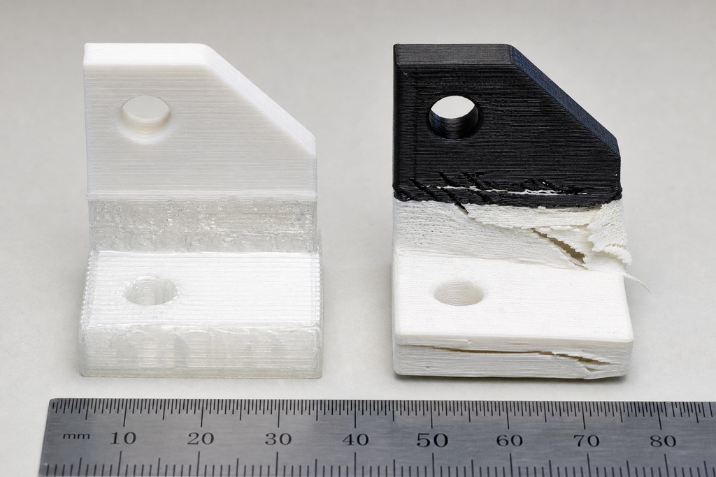
In single-nozzle systems, materials 30–40°C apart in nozzle temperature start creating purge and adhesion problems. A 90°C gap, PLA at 190°C and PA-CF at 280°C, is functionally incompatible on a shared-nozzle system.
In multi-head tool-changers, each head runs independently. So the constraint shifts from thermal compatibility to interface adhesion: will the two materials bond where they meet? That's a chemistry question, not a hardware one.
Real Material Pairings
Straightforward pairings are well-tested and forgiving. PLA + PVA (water-soluble support) is one of the most reliable multi-material combinations in FDM: both print near 190–220°C, and PVA dissolves cleanly in water. The catch: PVA absorbs atmospheric moisture and must be stored dry, or it degrades mid-print, causing clogs and inconsistent extrusion. PLA + breakaway support trades easy water-bath removal for simpler storage and handling. Same-polymer different colors carry zero compatibility concerns.
Intermediate pairings work with the right hardware. Rigid polymer + TPU (PLA or PETG housing with a flexible grip, hinge, or seal) is viable on multi-head systems where TPU's soft filament avoids sharing a melt zone. On single-nozzle systems, TPU can buckle and jam in the filament path due to its compressibility. A lesser-known pairing: PLA + PETG as support. PETG bonds weakly to PLA, which is actually an advantage: it makes excellent breakaway support that separates cleanly without chemical dissolution.
Known failure modes to avoid:
- PLA + ABS on a single nozzle: Different temperatures, different shrinkage rates, poor interface bonding. Delamination is expected.
- ABS + PVA: ABS's chamber and nozzle temperatures degrade PVA. UltiMaker testing recommends breakaway support for ABS instead.
- Polypropylene + any other polymer: PP adheres poorly to nearly everything. This is a material chemistry problem no hardware choice or slicer setting fixes.
- High-temp polymer + low-temperature support: The support degrades at the model material's processing temperature.
When polymers won't chemically bond at their interface, mechanical interlocking bridges the gap. PrusaSlicer's Multi-Material Interlocking generates a cross-hatched boundary layer between incompatible materials, creating mechanical bonds via geometry rather than chemistry. In CAD, beam interlocking with microscopic zipper/dovetail patterns at the material interface, undercuts, or lattice structures achieve the same result.
What Multi-Material Printing Enables
| Capability | Real Example |
|---|---|
| Rigid + flexible in one part | Housing with integrated gasket or living hinge |
| Soluble support for complex geometry | Hollow assembly with internal lattice channels |
| Full-color realistic prototypes | Anatomical model with color-coded tissue types |
| Functionally graded properties | PolyJet part varying 30A to 95A shore hardness in one wall |
| Embedded conductive traces | Printed circuits within a structural housing |
| Part consolidation | Multi-part bracket printed as one unit, eliminating failure points |
Harvard's MM3D research (Nature, November 2019) demonstrated a multi-material soft robot that moved at nearly 0.5 inches per second carrying 8× its own weight, and origami hinges withstanding over 1,000 folding cycles. Multi-material printing enables functional mechanisms, not just static prototypes.
Types of Multi-Material Combinations
All multi-material prints fall into distinct categories. Identifying which category your project belongs to determines compatible hardware, viable material pairs, and the design complexity you'll face.
Property-complementary pairs combine materials with different mechanical behaviors — a rigid housing with a flexible grip, a stiff frame with a compliant seal. These pairs are the signature capability of multi-material printing: one print replaces a multi-part assembly. The constraint is interface bonding. Materials that won't chemically adhere require mechanical interlocking strategies at their boundary.
Soluble and removable support pairs pair a structural polymer with a sacrificial one — PVA dissolves in water, breakaway materials peel away cleanly. These unlock geometric freedom (internal channels, trapped volumes, severe overhangs) that manual support removal can't reach. The support material must process at the model material's nozzle temperature without degrading.
Property-graded transitions blend material ratios continuously across a part, creating smooth stiffness or hardness gradients. This exists only on PolyJet systems via Digital Material blending. Consumer FDM cannot replicate it because each nozzle deposits one discrete material at a time.
Functional integration pairs embed materials for non-structural secondary purposes: conductive traces for printed circuits, magnetic or thermochromic filaments for sensing, or contrast filaments for alignment marks.
Each category maps to a hardware tier. Soluble support pairs work on single-nozzle filament changers. Property-complementary pairs need multi-head tool-changers or industrial jetting. Property grading is PolyJet-only. Buying hardware before identifying your combination type is the most common multi-material purchasing error.
Design, Slicing, and Software Workflow
Multi-material printing demands assigning materials at the design stage, not just at print time. Design each material region as a separate body in CAD (Fusion 360, SolidWorks, Rhino) with bodies overlapping or meeting at defined interfaces. Export as 3MF rather than disconnected STL files: 3MF preserves body relationships and origin alignment, while separate STL files require manual alignment in the slicer and are a common source of registration errors.
Slicers like PrusaSlicer, Bambu Studio, GrabCAD Print (Stratasys), or Cura with multi-material plugins assign materials to specific regions. In PrusaSlicer and Bambu Studio, import the 3MF, assign each body to a filament or extruder, then configure purge volume: higher values produce cleaner color transitions but more waste; lower values reduce waste but risk visible bleed between materials. Single-nozzle systems require a prime/purge tower to flush mixed material. GrabCAD Print (Stratasys) supports voxel-level material assignment for PolyJet, including Digital Material blends: a fundamentally different workflow where the slicer handles mixing ratios, not just region boundaries.
Designing and slicing multi-material parts requires advanced CAD and specialized slicing software (e.g., Stratasys GrabCAD Print) to define material zones, gradients, and interfaces. Software complexity is the hidden cost of multi-material printing. Single-material slicing is largely automated. Multi-material work requires CAD planning for material interfaces, slicer configuration for purge strategies, and manual review of tool paths so material transitions land at structurally appropriate positions. The learning curve is steeper but flattens once the logic clicks: assign bodies, configure transitions, verify interfaces.
Advantages and Limitations
Advantages:
| Advantage | What It Means in Practice |
|---|---|
| Part consolidation | One print replaces multi-part assemblies: fewer failure points, less labor |
| Functional grading | Smooth property transitions impossible with traditional manufacturing |
| Rapid multi-property prototyping | Realistic prototypes without post-assembly, painting, or overmolding |
| Complex geometry via soluble supports | Internal channels and hollow structures impossible to clean otherwise |
Limitations:
| Limitation | Root Cause | Severity |
|---|---|---|
| Purge waste | Shared melt zone in single-nozzle systems: physical, not tunable | High for single-nozzle; negligible for tool-changers |
| Print time increase | 30–42 sec per switch multiplied across dozens of layers | High for complex models |
| Material compatibility | Different thermal expansion, shrinkage, nozzle temps, adhesion chemistry | Moderate to fatal depending on pair |
| Cost | PolyJet: $50K–$300K+; consumer add-ons: $100–$5K; PolyJet materials proprietary | Varies by tier |
| Software complexity | Advanced CAD planning and specialized slicer configuration required | Moderate |
Choosing Your Approach
Multicolor (same polymer, different colors): Get a single-nozzle filament changer — Bambu Lab AMS or Prusa MMU3. Lowest cost, widest color range. Accept purge waste as the cost of simplicity. Don't pay for tool-changers or PolyJet. You need different spools, not different materials.
Rigid + flexible in one part: Go with a multi-head tool-changer (Prusa XL) or PolyJet. Single-nozzle systems can attempt PLA + TPU, but TPU jams in shared feed paths and its different flow rate causes oozing problems that waste time and filament.
Soluble supports for complex geometry: Single-nozzle filament changers handle PLA + PVA reliably. Budget for dry storage — PVA absorbs atmospheric moisture and degrades fast, turning from a clean support material into a clog generator.
Voxel-level property grading: Only PolyJet (Stratasys J-series) delivers this. Up to 14 materials simultaneously, Digital Material blends with custom stiffness and color. Hardware runs $50K–$300K+ plus proprietary material costs.
Multi-metal functionally graded parts: Directed Energy Deposition or Binder Jetting. These are industrial and research applications — not consumer-accessible as of 2025–2026.
Who Should NOT Use Multi-Material Printing
If your parts are structurally complete in a single polymer, multi-material hardware adds cost, complexity, and failure modes for zero benefit. If you only need color variety and don't mind painting afterward, a single-material printer and a brush beat managing purge waste. At production volumes, injection overmolding is cheaper per unit once tooling is amortized — multi-material 3D printing wins at prototyping and low-volume functional parts, not mass production. And if your filament budget is tight, purge waste from a single-nozzle system on complex multicolor prints can cost more in wasted material than the multi-material hardware upgrade itself.
Where This Technology Is Heading
Harvard's MM3D printhead (Nature, November 2019) demonstrated Y-shaped junctions inside the printhead that use pressure-tuned geometry to prevent backflow between ink channels. This enables material switching at up to 50 times per second — roughly three orders of magnitude faster than the 30–42 second switches in current desktop single-nozzle systems. Stratasys PolyJet already operates in simultaneous-deposition mode with up to 14 materials at once and no switching delay.
The research frontier is whether this simultaneous-deposition capability can reach lower price points and broader material libraries. The consumer space remains split between single-nozzle filament changers for color and multi-head tool-changers for genuinely different polymers. That split will persist until simultaneous-deposition technology gets dramatically cheaper.
FAQ
What is the difference between multi-material and multicolor 3D printing? Multicolor printing swaps filament colors within one polymer — mechanical and thermal properties stay identical. Multi-material printing combines polymers with different melt temperatures, stiffness, or flexibility, requiring compatible processing conditions and often different hardware to work reliably.
Can I print PLA and TPU together on a single-nozzle system? It's possible but unreliable. TPU's soft filament buckles in single-nozzle feed paths, and its different flow rate creates purge and oozing problems. A multi-head tool-changer or PolyJet system handles this combination reliably because TPU never shares a melt zone with rigid filament.
How much waste does multi-material FDM create? Single-nozzle systems generate significant purge waste — on complex multicolor models, purge can exceed the part's own filament weight. Tool-changer and PolyJet systems produce negligible switching waste because materials don't share a nozzle.
What slicer do I need for multi-material printing? PrusaSlicer and Bambu Studio handle FDM multi-material assignment with purge configuration. GrabCAD Print supports voxel-level material assignment for Stratasys PolyJet, including Digital Material blends. Cura with multi-material plugins also assigns materials to specific regions for supported hardware. All of them require you to design material regions as separate CAD bodies first.