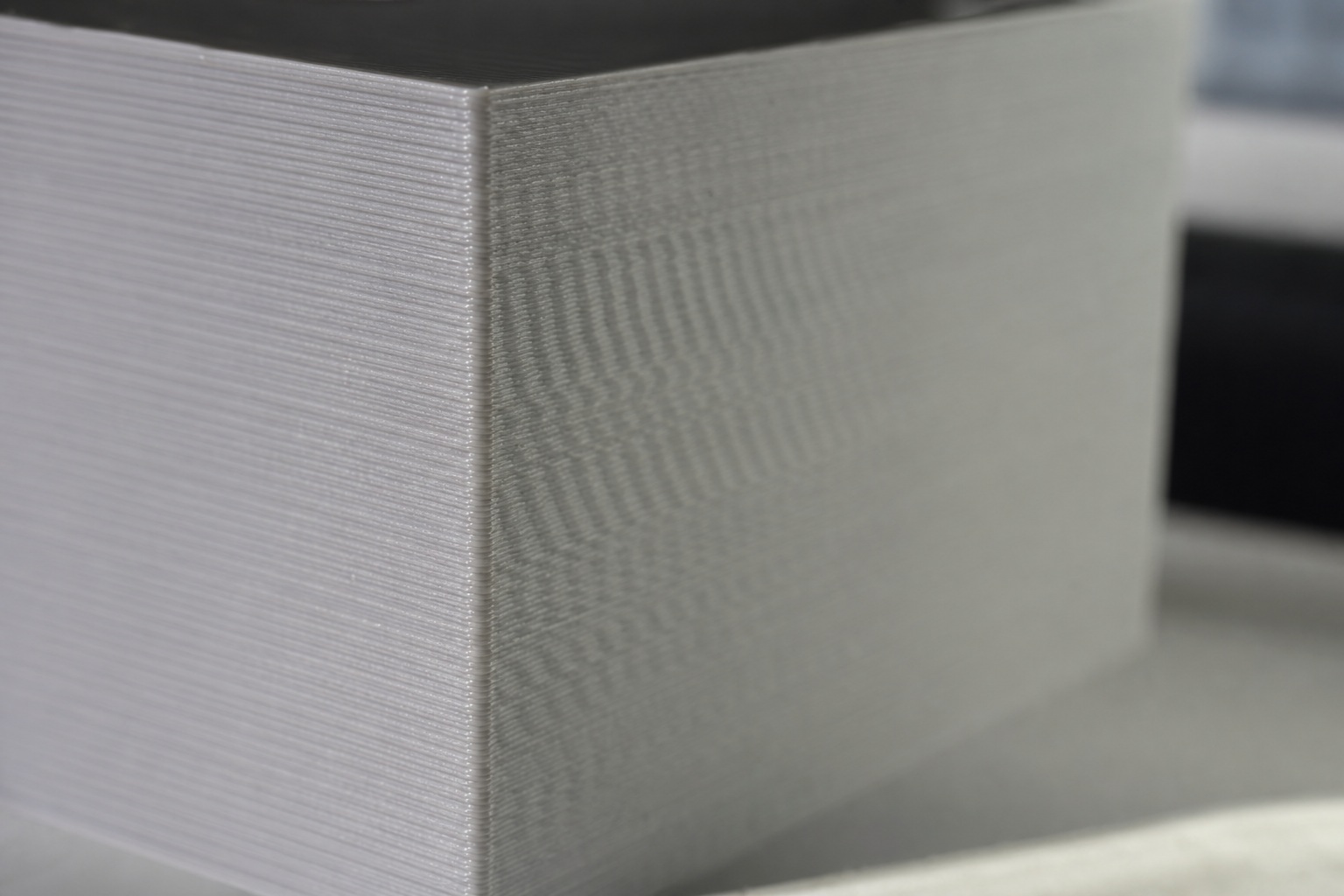
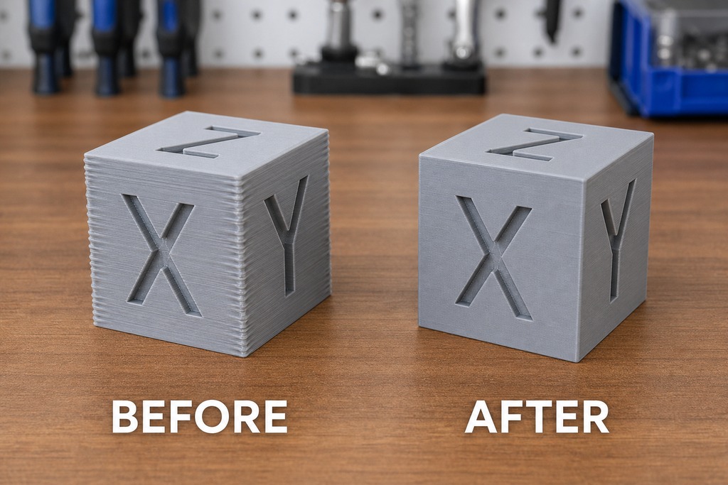
Those faint ripples trailing every sharp corner? Here's why they show up: and how to erase them. Input shaping calibration measures the resonant frequency of each printer axis, most precisely with an accelerometer like the ADXL345, then sets the firmware to cancel that vibration with the gentlest filter that does the job. Get it right and the ripples disappear. You can usually push acceleration several times higher and shave 20–50% off print time.
Most people treat input shaping as a quality patch you bolt onto any printer to erase ringing. It isn't. Ringing has two separate causes, and shaping only touches one of them. When the toolhead snaps direction, the frame, belts, and gantry flex and oscillate at their own natural frequency: that resonant vibration is what shaping cancels. But ringing also comes from actual looseness: a slack belt, a wobbly pulley, play in a carriage or a heat-block. No firmware fixes that. Calibrate on a loose machine and the software hands you numbers that are wrong or actively misleading. Input shaping is the final tuning step on a mechanically solid printer, not a shortcut around tightening it.
What Ringing and Ghosting Actually Are
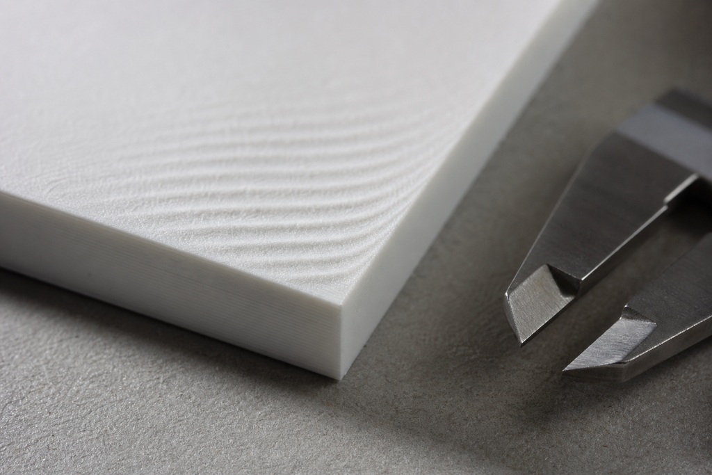
Ringing (also called ghosting or echoing) is the faint, repeating ripple pattern that appears just after a sharp corner or raised feature, fading as it moves away from the edge. It's the surface record of the toolhead overshooting and oscillating instead of stopping cleanly.
The cause is momentum. A rapid direction change dumps kinetic energy into the machine's structure, and every structure has a natural frequency at which it wants to vibrate. The nozzle then wobbles sideways to its travel while the belts and gantry ring like a struck bell, printing that oscillation into the wall as evenly spaced echoes. The effect grows with speed and acceleration, which is exactly why it sets a ceiling on how fast you can print before surface quality collapses. That ceiling is the problem input shaping is built to raise.
What Is Input Shaping
Input shaping is a feed-forward firmware technique that reshapes each motion command before it reaches the stepper motors, so the resulting vibration cancels itself. Nothing about the hardware changes; the correction lives entirely in software.
It's most closely tied to Klipper, which ships full measurement tooling, but Marlin 2.x and RepRapFirmware support it too. The term "shaping" is literal: the firmware alters the shape of the acceleration impulse, not the path the nozzle follows, so your dimensions stay correct while the wobble goes away.
How Input Shaping Cancels Vibration
Instead of sending one strong acceleration impulse, the firmware splits it into a short, precisely timed sequence of smaller impulses. The first impulse still excites the machine's resonance, but the next impulse is timed so its vibration arrives out of phase and cancels the first: destructive interference, the same trick that lets noise-cancelling headphones silence a hum.
Mathematically it's a convolution of the motion profile with an impulse train tuned to the measured frequency and damping ratio. That tuning is why calibration exists: the impulse spacing has to match your machine's exact resonant period. Feed it the wrong frequency and the second impulse can land in phase instead, amplifying the ringing rather than killing it. Get the frequency right and the vibration is gone in a fraction of a cycle.
Fix the Machine Before You Calibrate
Tighten and true the printer before you measure anything, because shaping compensates for resonance, not looseness: garbage in, garbage out. A slack belt or a rattling carriage produces a resonance graph full of false peaks, and any setting you pull from it is meaningless.
Run through this before touching a calibration command:
- Belts evenly and correctly tensioned on both X and Y
- Pulleys, idlers, and motor gears fully seated and set-screwed
- No detectable play when you wiggle the toolhead or the bed by hand
- Linear rails, bearings, or V-wheels rolling smoothly with no notchy spots
- Frame square, all structural bolts torqued
- Accelerometer mounted rigidly, not dangling on its wires
- Cables routed so nothing tugs the toolhead mid-move
- Printer sitting on the surface it normally runs on
One trap to avoid: don't crank belt tension to force a higher resonant frequency. Over-tensioned belts side-load bearings and motor shafts, wear them out early, and add new vibration modes of their own. Tension to the manufacturer's spec, then let calibration deal with whatever frequency results.
Calibration Methods
Two methods measure resonance: an accelerometer sweep and a printed ringing tower. The accelerometer method is objective and resolves frequency to under 1 Hz; the ringing-tower method needs no extra hardware but is subjective and approximate.
If you can borrow or buy an accelerometer, use it: it removes the guesswork and finishes in minutes. The tower method is a legitimate fallback when you have no sensor, but its accuracy rides on your eyes and a set of calipers, and unrelated print issues easily muddy it. Both feed the same [input_shaper] settings; they differ only in how the frequency is found.
Accelerometer Calibration Step by Step
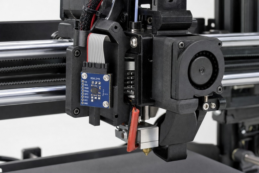
Mount an ADXL345 on the toolhead to measure X and on the bed to measure Y, then run Klipper's calibration sequence: the whole process takes roughly 10–15 minutes and lands within a fraction of a hertz.
- Mount and wire the sensor. The ADXL345 over SPI is standard; the LIS2DW, MPU-9250, and MPU6050 also work. Wire it to the printer's MCU or to a Raspberry Pi / Pico host, and move it from toolhead to bed when you switch axes.
ACCELEROMETER_QUERY: a self-test that confirms the sensor is wired correctly and returning live data.MEASURE_AXES_NOISE: reads background noise. Values under about 100 mean the mount and wiring are clean; higher numbers point to a loose sensor, running fans, or electrical interference that will corrupt the sweep.SHAPER_CALIBRATE: sweeps the axis across roughly 5–133 Hz while sampling at 3200 Hz, then analyzes the response. Run it per axis withAXIS=XorAXIS=Yif you want to isolate each one.- Read the recommendation, printed as a line like
Recommended shaper is mzv @ 52.4 Hz. Klipper picks the shaper and frequency that balance vibration reduction against smoothing for you. SAVE_CONFIG: writes the values into printer.cfg and restarts.
For a visual of the frequency response, the calibrate_shaper.py script turns the raw CSV into a labeled graph. It's worth generating the first time so you can see what your machine is actually doing.
The Ringing Tower Method
With no accelerometer, print a test model covered in sharp corners with input shaping turned off and acceleration set high enough to deliberately provoke ringing, then measure it directly. The tower steps its test frequency as it rises, so different heights excite the machine differently.
Find the band where the ghosting is worst or where a pattern is cleanest, measure the spacing between adjacent ripples with calipers, and calculate frequency = print speed ÷ ripple spacing. Enter that value into the axis's [input_shaper] setting, reprint, and iterate until the echoes fade. The method works, but treat its output as a starting estimate: extrusion inconsistency, pressure advance, and any leftover mechanical play all distort the ripple pattern and can send you chasing a frequency that isn't real.
Choosing a Shaper Type
Pick the least aggressive shaper that adequately suppresses your resonance, because stronger suppression always costs more smoothing: and more smoothing rounds corners and blurs fine detail. A "more powerful" shaper isn't a better one; it's a trade you make only when you need the extra robustness.
| Shaper | Vibration reduction | Smoothing / corner rounding | When to use |
|---|---|---|---|
| ZV (Zero Vibration) | Lowest | Least | Stiff, well-damped machines where detail matters; least tolerant of frequency drift |
| MZV | Good | Low | The common default for most Cartesian and CoreXY printers |
| ZVD | Better | Medium | When you want more tolerance to frequency error than ZV gives |
| EI (Extra Insensitive) | High | More | Broad resonance peaks or uncertain frequency |
| 2HUMP_EI | Very high | High | Multiple nearby resonances, or a very low frequency |
| 3HUMP_EI | Highest | Highest | Severe or very broad resonance; rarely needed |
The calibration script defaults to whichever of these clears the resonance with the least smoothing, and that recommendation is almost always the right one. Override it only when you have a specific reason: say, a belt that drifts in tension and pushes you toward EI's wider tolerance.
Reading the Resonance Graph
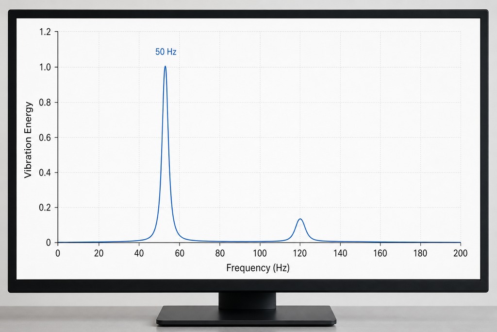
The plot puts vibration energy on the vertical axis and frequency in hertz on the horizontal axis; the tallest peak marks your dominant resonance and becomes your shaper frequency. The shape around that peak tells you whether the machine is ready to shape or still needs work.
A tall, narrow peak is the ideal: one clean, well-defined resonance the shaper can target precisely. Several distinct peaks mean multiple structures are vibrating, or something is mechanically loose, so rule out looseness before you accept the result. A single broad, rounded hump usually points to heavy damping or coupled components moving together. Data that looks noisy or nonsensical almost always traces back to hardware, not the printer's motion: a loose sensor mount, wiring picking up interference, or a fan feeding vibration into the accelerometer.
Frequency Is Not Acceleration
Shaper frequency and acceleration are different quantities, related only indirectly, and confusing them leads to bad settings. Frequency, in hertz, describes how fast the machine vibrates. Acceleration, in mm/s², describes how fast the toolhead changes velocity. A printer might have a 45 Hz Y resonance and run 5,000 mm/s² acceleration: neither number sets the other.
They connect only through cause and effect: higher acceleration excites the resonance more violently, and the shaper is timed to cancel that resonance whatever the acceleration. This matters because calibration also reports a suggested maximum acceleration, and that figure is a smoothing-based estimate, the point where the shaper's corner-rounding becomes objectionable, not proof the printer can move that fast. Motor torque, belt grip, achievable flow rate, and layer adhesion all impose real limits that may sit well below the reported number.
Typical Numbers and What to Expect
Most desktop FDM printers resonate somewhere between 30 and 80 Hz, with X often landing around 30–70 Hz and Y around 20–50 Hz — though sources vary, and a range of 20–80 Hz covers nearly all of them. Bed-slingers show a lower Y frequency because the moving mass is the whole heated bed plus the part; CoreXY machines tend toward higher X and Y frequencies that sit closer together, since neither axis drags a heavy bed.
After calibration, acceleration commonly climbs from a stock 500–1,500 mm/s² up toward 3,000–10,000 mm/s² or more, and print times typically drop 20–50% depending on how many corners and travel moves a model contains. Treat the high end with caution: some references put the realistic gain closer to 2,000–5,000 mm/s², and the true limit is machine-dependent for the torque and flow reasons above. The damping ratio parameter defaults to about 0.1 (real machines fall between 0.05 and 0.15) and is almost always left alone — measuring it precisely adds effort for little return.
Klipper vs Marlin vs RepRapFirmware
All three firmwares support input shaping, but they differ sharply in how much they automate. Klipper measures and recommends for you; Marlin and RepRapFirmware expect you to arrive with a frequency already in hand.
| Firmware | Shaper support | Calibration method | How you set it |
|---|---|---|---|
| Klipper | Full accelerometer sweep, auto-recommends shaper and frequency | Accelerometer (ADXL345) via SHAPER_CALIBRATE |
Written to printer.cfg by SAVE_CONFIG |
| Marlin 2.x | ZV shaper, enabled in Configuration_adv.h (INPUT_SHAPING_X/Y) |
Mainly the ringing tower | M593 F<freq> D<damping> |
| RepRapFirmware | Supported, multiple shaper types | Accelerometer or manual; documented workflow is thinner than Klipper's | M593 |
If your priority is the easiest, most accurate path, Klipper is the reference case for a reason. On Marlin, budget time for the ringing tower unless you have accelerometer tooling configured, and remember it defaults to a single ZV shaper. RepRapFirmware sits in between (capable, but with less hand-holding) so check its current documentation for the exact steps rather than assuming Klipper's workflow carries over.
When to Recalibrate
Recalibrate whenever the moving mass changes, because mass directly sets the resonant frequency the shaper is tuned to. A new hotend, a direct-drive conversion, an added probe, a filament sensor on the toolhead, or a belt swap all shift the numbers enough that yesterday's settings no longer cancel today's vibration.
Confirm the result with a before-and-after ringing tower — the print itself is the honest test, not the graph. One easy-to-miss detail: if you used a heavy accelerometer for calibration, remove it afterward. Leaving it on the toolhead adds mass and shifts the very frequency you just measured, quietly undoing part of the tuning.
Who Should Not Rely on Input Shaping
Skip or postpone input shaping if your ringing traces to loose mechanics, if the recommended frequency comes back very low, or if you're treating the reported max acceleration as a guaranteed speed. In each case, shaping is the wrong tool or a premature one.
- Loose or worn mechanics. If ringing survives a correct calibration, the source is almost certainly mechanical — a slack belt, worn bearing, or wobbly carriage. Shaping can't compensate for play; fix it physically.
- A recommended frequency below ~20 Hz. This is the honest signal that the machine is too flexible or too loose. The answer is to stiffen and tighten it, not to accept the low setting and live with the heavy smoothing it forces.
- Chasing detail with an aggressive shaper. More suppression rounds corners. If fine features are blurring, you've over-shaped; step down to a gentler algorithm.
- Masking other faults. Extrusion inconsistency, missed steps, and vertical fine artifacts have their own separate fixes. Input shaping is one step in tuning, not the whole of it, and it won't hide those problems.
FAQ
How do I know if my z-offset is correct?
Your z-offset is right when the first layer lines are pressed lightly together into a smooth, even sheet — not translucent and gapped (nozzle too high) and not gouged or ridged (nozzle too low). The paper-drag test gets you close: you should feel slight resistance on a sheet under the nozzle at Z0. This is entirely separate from input shaping; it governs nozzle-to-bed distance, not vibration, and doesn't affect ringing.
How to calibrate Input Shaping klipper?
Mount an ADXL345 to the toolhead, run ACCELEROMETER_QUERY to confirm it responds, then MEASURE_AXES_NOISE (values should read under about 100). Run SHAPER_CALIBRATE, which sweeps roughly 5–133 Hz and recommends a shaper and frequency, then SAVE_CONFIG to store it. Repeat with the sensor on the bed for the Y axis; the whole process takes about 10–15 minutes.
Do you need an accelerometer for Input Shaping?
No. The ringing-tower method calibrates input shaping without any sensor — you print a test, measure the ripple spacing with calipers, and compute frequency from print speed divided by that spacing. An accelerometer is strongly preferred, though, because it's objective and resolves frequency to under 1 Hz, while the tower method is subjective and easily thrown off by extrusion, pressure advance, or loose mechanics.
What is the 45 degree rule in 3D printing?
The 45-degree rule says overhangs up to about 45° from vertical print reliably without support, because each new layer still rests mostly on the one below it; steeper overhangs sag and usually need support. It's a bridging-and-overhang guideline and has nothing to do with input shaping or resonance — a separate topic entirely.
References
- Klipper Documentation — Measuring Resonances and Kinematics (accelerometer setup,
SHAPER_CALIBRATE, sweep range, shaper types, damping ratio defaults). - Marlin Firmware Documentation — Input Shaping configuration and the
M593command. - RepRapFirmware Documentation — Input shaping support and
M593usage. - Analog Devices — ADXL345 3-axis accelerometer datasheet (SPI interface, sampling capability).